Worked example: designing a 148,790-element nuclear island to Eurocode 2
A full design run, step by step: 148,790 shell elements and 96 load cases designed to Eurocode 2, with the plots, a validation calculation and a 3D review, and every number taken from the run itself.
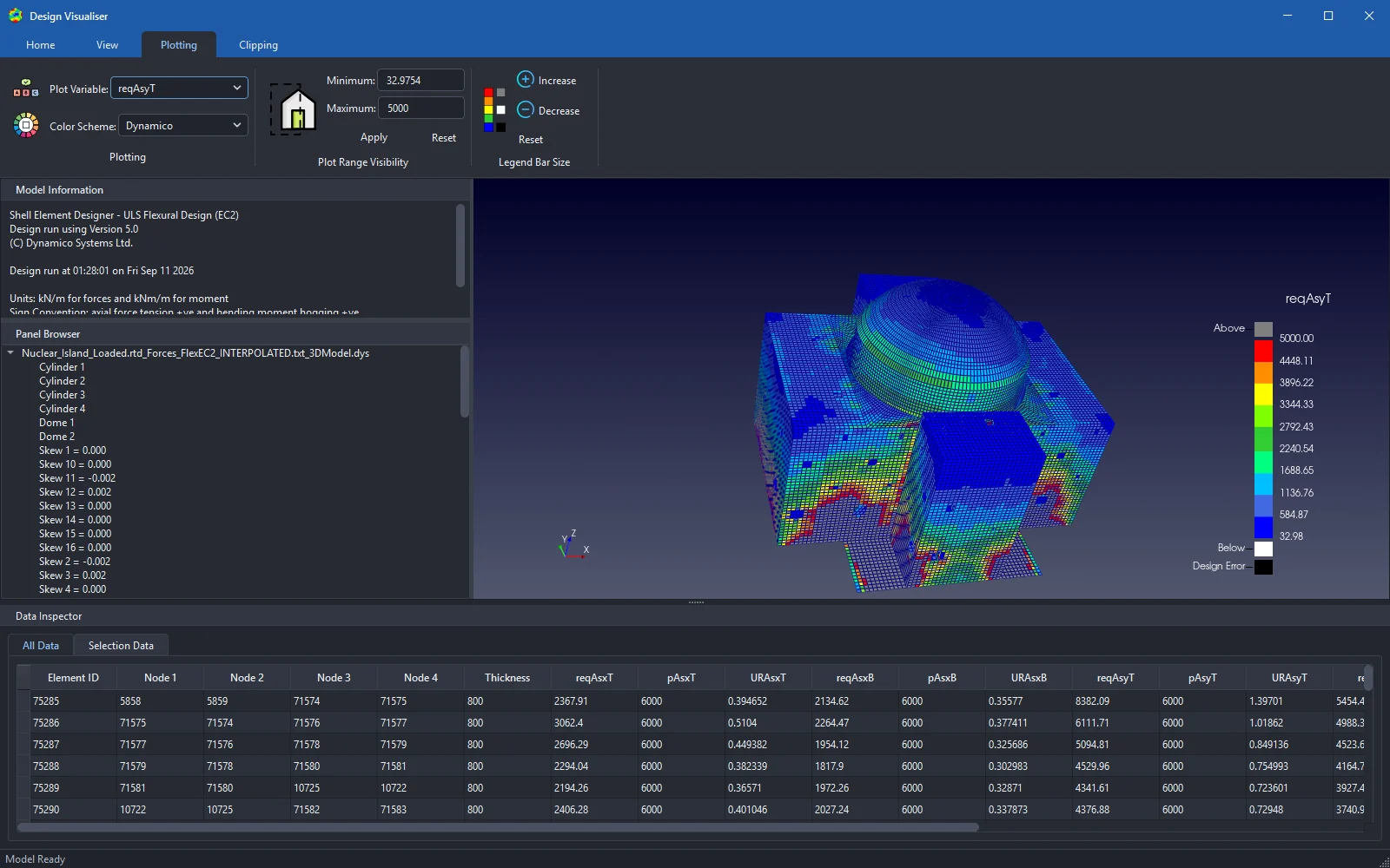
This article follows one complete design run in Shell Element Designer, from the analysis model to a reviewed 3D result. The model is a demonstration nuclear island built from conceptual, public-source geometry: a 100 m by 100 m common raft on soil springs, a double containment with two domes, and the internal floors and walls around it. Every figure below comes from the run’s own log and outputs.
- 148,790shell elements
- 140,591nodes
- 96load cases
- 301 sdesign calculation time
1. The analysis model
The structure was analysed in Autodesk Robot Structural Analysis. Shell Element Designer does not perform analysis; it designs from the results you already have, whichever package produced them.

2. Input files, checked before the run
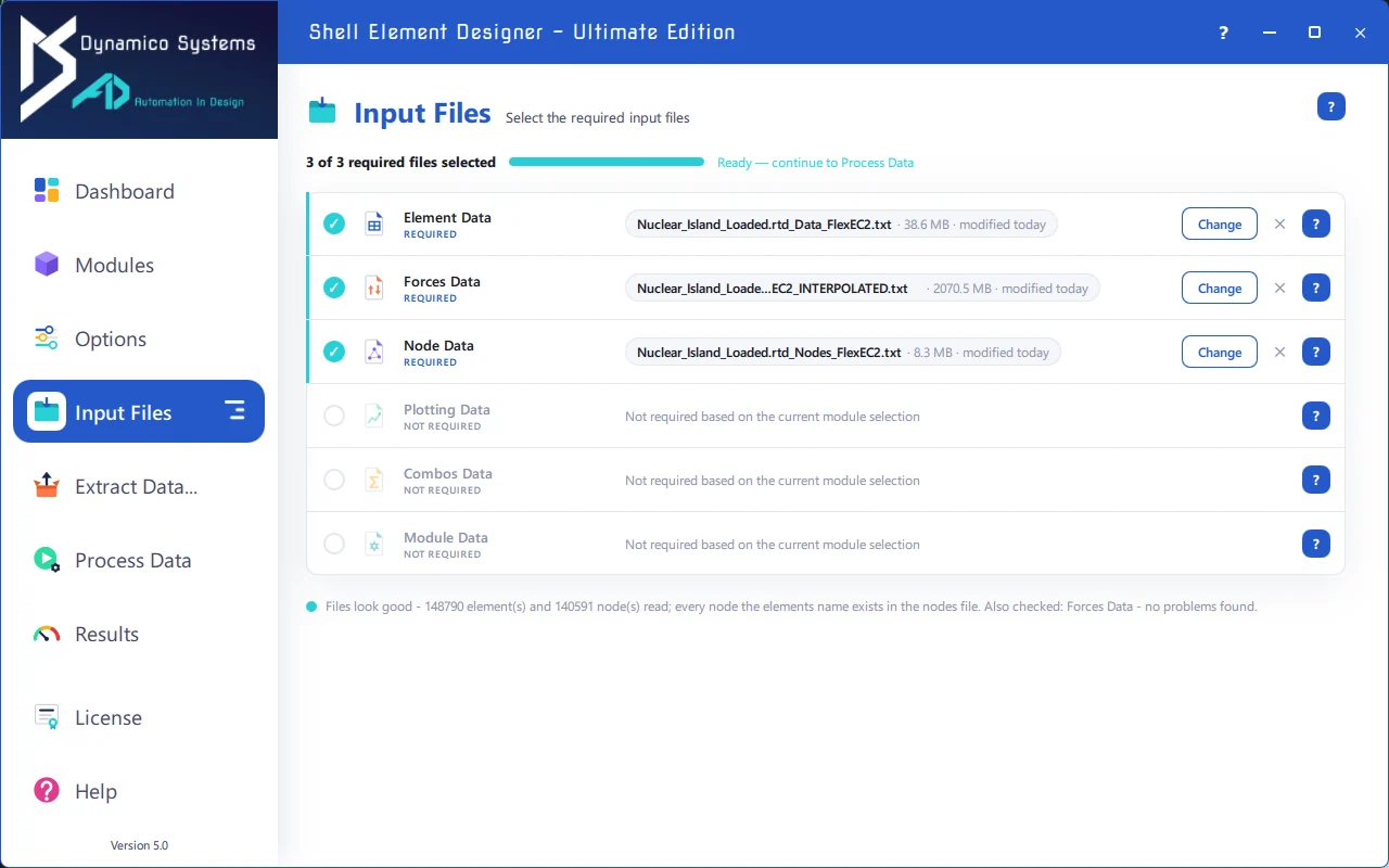
The element, forces and node data are exported as plain-text files. The forces file for this model is 2.1 GB: one row per element for each of the 96 loads, 14.3 million rows in all. As the files are selected, the software checks them in the background: every element read, every node the elements name present in the nodes file, and the forces consistent with both.
3. The design run
We ran ULS flexural design to Eurocode 2 with automatic plots. Reading the 2.1 GB forces file took 78 seconds. The design itself, every element for every load case, about 14.3 million element designs, took 301 seconds. Writing the complete results took a further 290 seconds.
From the bare mesh, the software recognised 62 panels automatically, including four cylindrical walls and two domes. Keeping curved walls and domes whole as single curved panels, rather than cutting them into flat pieces, is coming in the next release.
4. The outputs
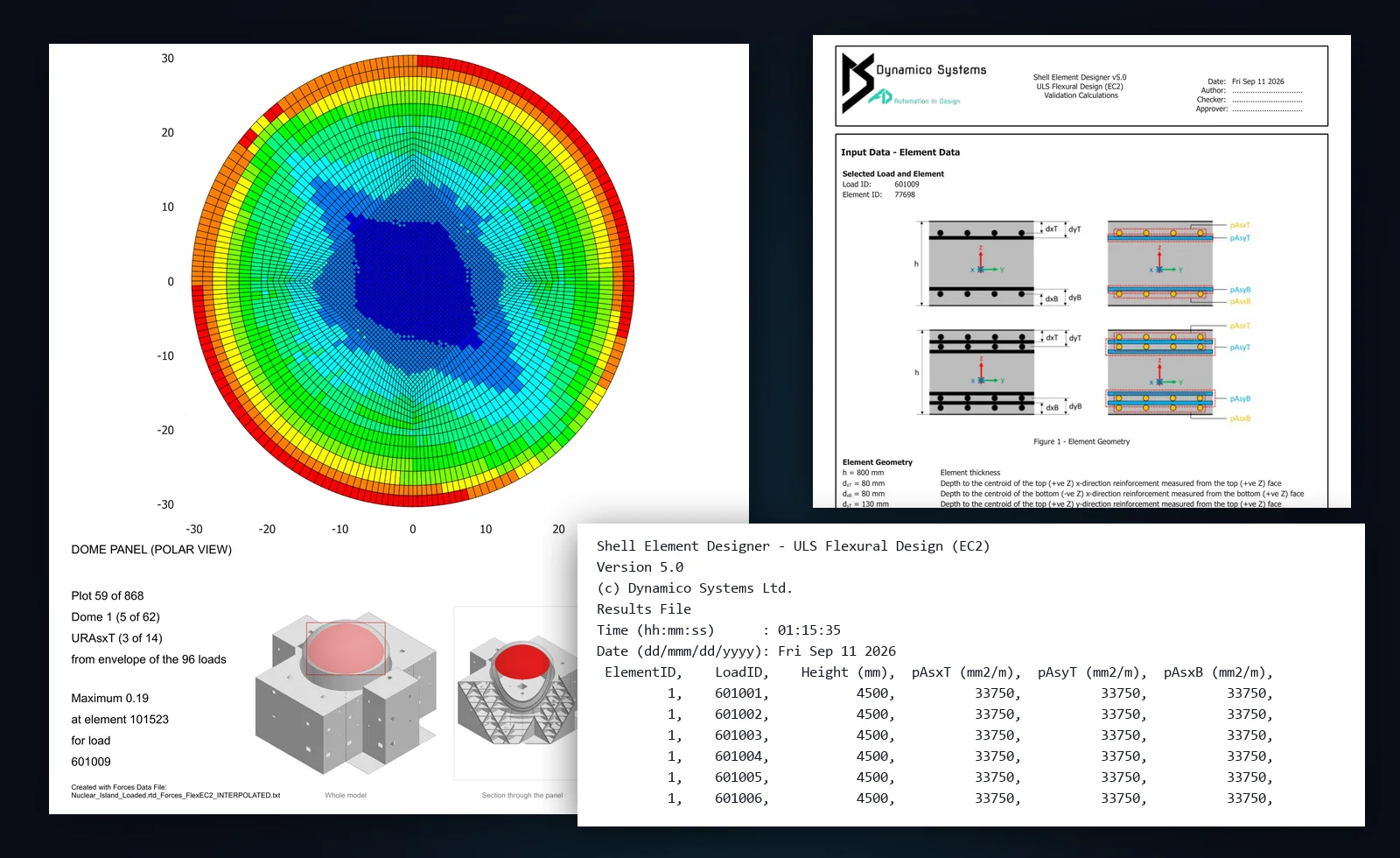
The run produced 868 pages of contour plots, one for each panel and design variable, each with the maximum value, the element it occurs at and its governing load, and a 3D picture of the whole model showing where the panel sits. With the next release, domes are plotted as a disc seen from above the crown and cylinders are unrolled, so lengths on the plot are true surface lengths.
5. Checking one element by hand
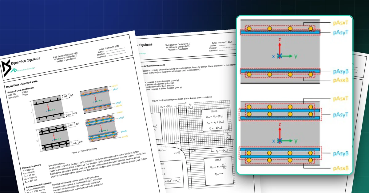
On the first cylindrical wall, the largest required top-face reinforcement in the x direction is 3,332.31 mm²/m, at element 77698 under load 601009. We asked for the validation calculation for that element and load: a 12-page PDF that sets out the geometry, the applied forces, the sandwich layer thicknesses and forces, and the reinforcement, step by step. Its final result is 3,332.31 mm²/m, exactly the value on the plot.
6. Reviewing the design in 3D
The run also writes a 3D model file that opens in the Design Visualiser. With value clipping, everything below a chosen threshold disappears, so the elements that drive the reinforcement stand out, and clicking any element shows its full results row.

What this shows
A structure of this size is designed in minutes, not weeks, and nothing about the result has to be taken on trust: the inputs are checked, the working for any element is available as a hand calculation, and the plots, the calculation and the raw data all agree. See how the workflow fits yours.